
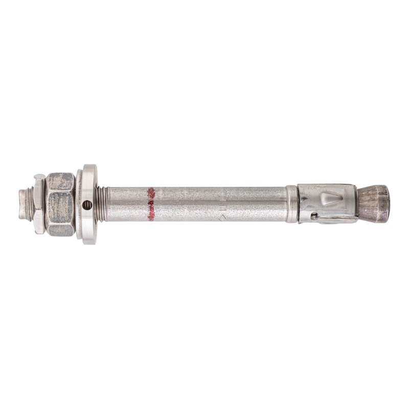
Fixanchor W-FAZ PRO dynamic/A4
Fixanchor W-FAZ PRO Dynamic A4 stainless steel
ANC-(W-FAZ PRO DYN/A4)-A4-50-M16X180
Art.-no. 5930441650
EAN 4099618127809
Register now and access more than 125,000 products
- Fixanchor for use as an individual fixing point subject to (dynamic) fatigue loading in concrete
- Simple, fast and secure installation with dynamic set
- Enables extremely efficient application
- Enables installation with minimum spacing and edge distances
- High performance even when subjected to static loads, seismic activity and fire exposure
European Technical Assessment ETA-20/0486
- Static or quasi-static loads
- Seismic activity, performance categories C1 and C2
- Fire resistance R30, R60, R90, R120
- Individual fixing point subject to cyclic fatigue loading
Datasheets(X)

Individual fixing point subject to fatigue loading in pre-positioned or in-place installation
Individual fixing point subject to static or quasi-static loads, seismic activity and fire exposure
Base material:
- Reinforced and non-reinforced normal weight concrete without fibres
- Cracked or uncracked concrete
- Concrete compressive strength: C20/25 to C50/60
Heavy-duty fixing points for dynamic loading in concrete
Suitable for anchoring fixtures subject to cyclic fatigue loading, e.g. crane tracks, slewing cranes, fans, machines, robots, conveyor systems, lift guide rails, traffic control systems along railways, roads and in tunnels.
W-FAZ PRO/A4 (A4 stainless steel) may be used in dry indoor areas and under all other conditions in accordance with EN 1993-1-4:2015-10 annex A, table A.3: CRC I-III
Metric anchor diameter | M16 |
Anchor length (l) | 180 mm |
Min./max. height of the fixture (t fix) | 25-50 mm |
Attachment height (t fix) | 50 mm |
Effective anchoring depth (h ef) | 85 mm |
Disc diameter x disc thickness | 30 x 3 mm |
Width across flats | 24 mm |
Nominal drill-bit diameter (d 0) | 16 mm |
Drill hole depth (h 1) | 102 mm |
Material | Stainless steel A4 |
Surface | Coated |
Torque during anchoring (T inst) | 100 Nm |
Through-hole in the component to be connected (d f) | 18 mm |
Thread type x anchor diameter x thread length (L th) | M16 x 54 |
Approval | ETA-20/0486, ETA-20/0229 |
Seismology C1 | Yes |
Seismology C2 | Yes |
| Performance data without axial influence and the influence of the edge distance under cyclic fatigue loading according to ETA-20/0486 | |||||
| Anchor size | [mm] | M10 | M12 | M16 | |
| Effective anchorage depth | hef | [mm] | 60 | 70 | 85 |
| Individual fixing point for cracked and uncracked concrete | |||||
| Admissible tension load in concrete ≥ C20/25 1) | ΔNadm | [kN] | 2,4 | 3,9 | 6,8 |
| Admissible shear load in concrete ≥ C20/25 1) | ΔNadm | [kN] | 1,1 | 2,1 | 4,4 |
| Fixing group for cracked and uncracked concrete | |||||
| Admissible tension load in concrete ≥ C20/25 1) | ΔNadm | [kN] | 1,2 | 1,96 | 3,4 |
| Admissible shear load in concrete ≥ C20/25 1) | ΔNadm | [kN] | 0,55 | 1,0 | 2,2 |
| Static and quasi-static load, fire load and seismic load, refer to European technical assessment ETA-20/0486 and 1) Admissible loads in accordance with EN 1992-4 without influences of axis and edge distances. The overall safety factor has been taken into account. | |||||
| Installation parameters1) | |||||
| Anchor size | [mm] | M10 | M12 | M16 | |
| Effective anchorage depth | hef ≥ | [mm] | 60 | 70 | 85 |
| Minimum member thickness | hmin ≥ | [mm] | 90 | 105 | 127,5 |
| Minimum spacing | smin | [mm] | 40 | 50 | 65 |
| Minimum edge distance | cmin | [mm] | 45 | 55 | 65 |
| Nominal drill dia. | d0 | [mm] | 10 | 12 | 16 |
| Diameter of cutting edges | dcut ≤ | [mm] | 10,45 | 12,5 | 16,5 |
| Drill hole depth 2) | h0 ≥ | [mm] | 69 | 80 | 99 |
| h1 ≥ | [mm] | 71 | 83 | 102 | |
| Through hole in the fixture | df ≤ | [mm] | 12 | 14 | 18 |
| Hexagon nut width across flats | AF | [mm] | 17 | 19 | 24 |
| Nyloc nut width across flats | AF | [mm] | 17 | 19 | 24 |
| Torque while installing anchor | Tinst = | [Nm] | 40 | 55 | 100 |
| Overhang | hp | [mm] | 21.5 + tfix | 25.5 + tfix | 29.5 + tfix |
| Height of the hexagon nut | tnut | [mm] | 8 | 10 | 13 |
| Washer diameter | dw x tw | [mm] | 20 x 2 | 24 x 2.5 | 30 x 3 |
| Filling washer diameter x height | dWIT-SHB x tWIT-SHB | [mm] | 26 x 5 | 28 x 5 | 34 x 4 |
| 1) For anchor groups and anchorings close to the edge, the combinations of the minimum values (member thickness, spacings and edge distances) and the associated loads must be determined in accordance with the calculation methods of the European Technical Assessment (ETA-20/0486). | |||||
| 2) If the maximum clamping thickness tfix,max is not fully reached, the drill hole depth can be increased by the appropriate dimension and the anchor can be installed deeper. In in-place installation, the result is h1,d=h1+tfix,max. In pre-positioned installation, the result is h1,v=h1+(tfix,max - tfix). The specified tfix,min must be observed. The end of the thread must always be above the concrete surface. | |||||